
| PARTS LIST | ||
|---|---|---|
| REF # | PART # | DESCRIPTION |
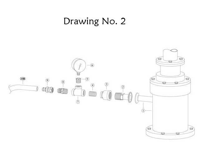
| 2-1 | —— | Existing Counterpressure Rotary Joint |
| 2-2 | ULT-58-A | S/S Male Pipe Adapter (1-1/2″) |
| 2-3 | ULT-58-B | 1″x1/2″ S/S Reducing Coupling |
| 2-4 | ULT-50 | 1/2″ x Close S/S Nipple |
| 2-5 | ULT-52 | 1/2″ x 1/4″ S/S Reducing Bushing |
| 2-6 | ULT-61 | Pressure Gauge 0-100# S/S |
| 2-7 | ULT-62 | 1/2″ x 1/2″ x 1/2″ S/S Tee |
| 2-8 | ULT-30 | 1/2″ x 1/2″ Hose Connector |
| 2-9 | ULT-31 | 1/2″ Swivel Hose Connector |
| 2-10 | ULT-32 | 1/2″ I.D. Hose |

| PARTS LIST | ||
|---|---|---|
| REF # | PART # | DESCRIPTION |
| 3-1 | ULT-29 | 1/4″ O.D. Tubing |
| 3-2 | ULT-40-N | 90 Degree Tubing Connector (2 pcs. req.) |
| 3-3 | ULT-42-S | Valve Actuator |
| 3-4 | ULT-28-N | 1/16″ Barb Fitting |
| 3-5 | ULT-55-BK | 1/16″ I.D. Black Tubing-Connect to 7-H, (dwg.#7) |
| 3-6 | ULT-43-S | 1/8″ x Close S/S Nipple |
| 3-7 | ——- | Existing Product Line |
| 3-9 | ULT-37-A | Counterpressure Valve Mounting Bracket |
| 3-10 | ULT-30 | 1/2″ x 1/2″ Hose Connector (4 pcs. req.) |
| 3-11 | ULT-31 | 1/2″ Swivel Hose Connector (4 pcs. req.) |
| 3-12 | ULT-32 | 1/2″ I.D. Hose |
| 3-13 | ULT-36-S1 | Counterpressure Valve |
| 3-14 | ULT-37-B | 1/4″ – 20 S/S U-Bolt (2 pcs. req.) |
| 3-15 | ULT-02 | 1/4″ -20 S/S Nut (4 pcs. req.) |
| 3-16 | ULT-50 | 1/2″ x Close S/S Nipple |
| 3-17 | ULT-49 | 1/2″ S/S Cross |
| 3-18 | ULT-52 | 1/2″ x 1/4″ S/S Reducing Bushing |
| 3-19 | ULT-53 | 1/4″ x Close S/S Nipple |
| 3-20 | ULT-39 | 1/4″ Air Filter – 5 Micron |
| 3-21 | ULT-44-S | 1/4″ x 1/8″ S/S Reducing Bushing |
| 3-22 | ULT-38-S | Pressure Gauge 0-60# S/S |
| 3-23 | ULT-57-B | 1/4″-20 x 1″ S/S Flat Head Screw (2 pcs. req.) |
| PARTS LIST | ||
|---|---|---|
| REF # | PART # | DESCRIPTION |
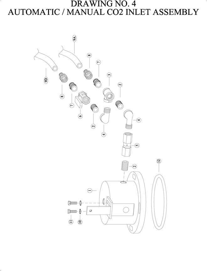
| 4-1 | ULT-58 | Lid Canister (“CAP”) |
| 4-2 | ULT-50 | 1/2″ x Close S/S Nipple (3 pcs. req.) |
| 4-3 | ULT-62 | 1/2″ x 1/2″ x 1/2″ S/S Tee |
| 4-4 | ULT-47 | 1/2″ S/S Street Elbow (2 pcs. req.) |
| 4-5 | ULT-46 | 1/2″ S/S Check Valve |
| 4-6 | ULT-51 | 1/2″ S/S Ball Valve |
| 4-7 | ULT-30 | 1/2″ x 1/2″ Hose Connector (2 pcs. req.) |
| 4-8 | ULT-31 | 1/2″ Swivel Hose Connector (2 pcs. req.) |
| 4-9 | ULT-32 | 1/2″ I.D. Hose |
| 4-10 | ULT-59-A | 5/16″ S/S Lockwasher (2 pcs. req.) |
| 4-11 | ULT-59-B | 5/16″ x 18″ x 34″ S/S Bolt (2 pcs. req.) |
| 4-12 | ULT-63 | Lid Canister “O” Ring |

| PARTS LIST | ||
|---|---|---|
| REF # | PART # | DESCRIPTION |
| 5-2 | ULT-52 | 1/2″ x 1/4″ S/S Reducing Bushing |
| 5-3 | ULT-47 | 1/2″ S/S Street Elbow |
| 5-4 | ULT-51-A | 1/2″ S/S Ball Valve w/Gauge |
| 5-5 | ULT-70 | 1/4″ x 3″ S/S Nipple |
| 5-6 | ULT-54-C | 1/4″ S/S Vent Valve |
| 5-7 | ULT-43-S | 1/8″ x Close S/S Nipple (2 pcs. req.) |
| 5-8 | ULT-73 | 1/8″ Shuttle Valve |
| 5-9 | ULT-42-S | Valve Actuator |
| 5-10 | ULT-29 | 1/4″ O.D. Tubing |
| 5-11 | ULT-41-N | Tee Tubing Connector |
| 5-12 | ULT-55-WH | 1/16″ I.D.White Tubing(Connect to 8-G, DWG.#7) |
| 5-13 | ULT-28-N | 1/16″ Barb Fitting |
| 5-14 | ULT-40-N | 90 Degree Tubing Connector |
| 5-15 | ULT-50 | 1/2″ x Close S/S Nipple |
| 5-16 | ULT-58 | Lid Canister (“CAP”) |
| 5-17 | ULT-72 | 1/4″ S/S Street EL |
| PARTS LIST | ||
|---|---|---|
| REF # | PART # | DESCRIPTION |
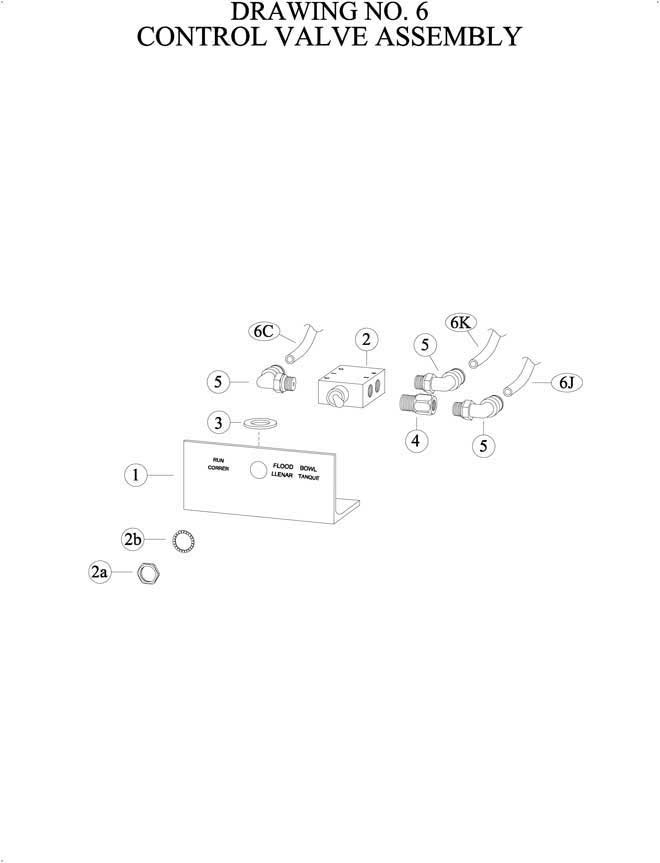
| 6-1 | ULT-74 | Control Mounting Bracket |
| 6-2 | ULT-75 | Control Valve |
| 6-2a | * | 15/32 Nut |
| 6-2b | * | 15/32 Internal Tooth Lock Washer |
| 6-3 | ULT-77 | 1/2″ S/S Flat Washer |
| 6-4 | ULT-76 | 1/8″ x 1/8″ Extender |
| 6-5 | ULT-40-N | 90 Degree Tubing Connector (3 pcs. req.) |
| 6-6 | ULT-29 | 1/4″ O.D. Tubing |
| * SUPPLIED WITH ULT-75 (6-2) | ||
| PARTS LIST | ||
|---|---|---|
| REF # | PART # | DESCRIPTION |
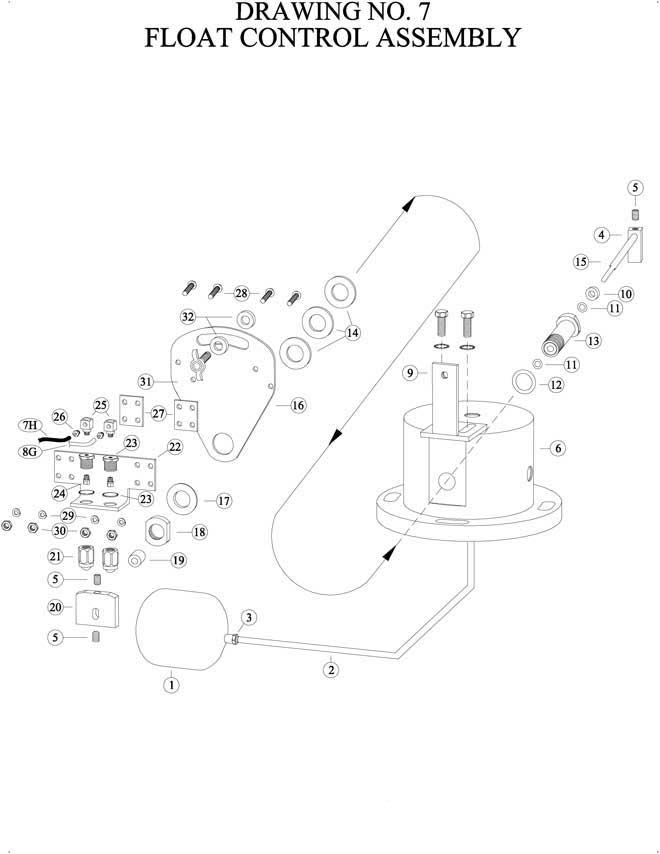
| 7-1 | ULT-01 | Float Ball |
| 7-2 | ULT-03-MS | Float Stem |
| 7-3 | ULT-02 | 1/4-20 S/S Nut (2 pcs. req.) |
| 7-4 | ULT-04-A | Float Arm Hub |
| 7-5 | ULT-19 | 1/4″-20 x 3/8″ S/S Set Screw (3 pcs. req.) |
| 7-6 | ULT-58 | Lid Canister (“CAP”) |
| 7-7 | ULT-55-BK | 1/16″ I.D. Black Tubing (Connect to 5-H, Dwg. #3) |
| 7-8 | ULT-55-WH | 1/16″ I.D. White Tubing (Connect to 12-G, Dwg. #5) |
| 7-9 | ULT-59 | Stationary Bracket |
| 7-10 | ULT-05 | Spacer |
| 7-11 | ULT-05-A | Teflon Coated “O” ring (2 pcs. req.) |
| 7-12 | ULT-07-M | “O” Ring |
| 7-13 | ULT-06-1-M | Float Shaft Hub |
| 7-14 | ULT-08-M | Spacer Washer (3 pcs. req.) |
| 7-15 | ULT-04-MS | Float Arm Shaft |
| 7-16 | ULT-13-MS | Movable Adjusting Plate |
| 7-17 | ULT-09-M | Support Bushing |
| 7-18 | ULT-16-M | Float Shaft Hub Nut |
| 7-19 | ULT-18-A | Cam Block Spacer (.625″) |
| 7-20 | ULT-20 | Cam Block |
| 7-21 | ULT-21-N | Actuator Ball & Housing (2 pcs. req.) |
| 7-22 | ULT-22-MS | Actuator B&H Mounting Bracket |
| 7-23 | ULT-27-N | Housing with Star Washer (2 pcs. req.) |
| PARTS LIST | ||
|---|---|---|
| REF # | PART # | DESCRIPTION |
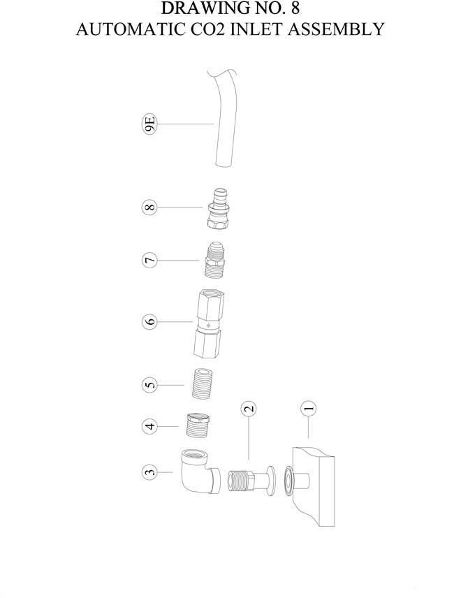
| 8-1 | —– | Existing Filler Bowl |
| 8-2 | ULT-58-A | S/S Male Pipe Adapter (1-1/2″) |
| 8-3 | ULT-80 | 1″ S/S Elbow |
| 8-4 | ULT-80-A | 1″x 1/2″ S/S Bushing |
| 8-5 | ULT-50 | 1/2″ x Close S/S Nipple |
| 8-6 | ULT-46 | 1/2″ S/S Check Valve |
| 8-7 | ULT-30 | 1/2″ x 1/2″ Hose Connector |
| 8-8 | ULT-31 | 1/2″ Swivel Hose Connector |
| 8-9 | ULT-32 | 1/2″ I.D. Hose |