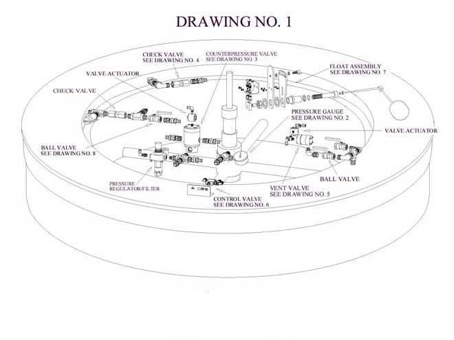
Crown Level Control System
Universal’s “Uni-Level-Trol®” system is a single float control system that will allow higher production speeds by maintaining a constant optimum product level in the filler bowl.
System Highlights
- The liquid level in the filler bowl is basically controlled by the pressure balance between the filler bowl and the carbo-cooler or carbonator. When the pressure between the two are equal, there is no flow, due to static balance.
- When the pressure between the two are equal, there is no flow, due to static balance.
- When the pressure in the filler bowl is less than the carbo-cooler the liquid in the carbo-cooler will flow into the filler bowl until the pressure is equalized.
- If the pressure is greater in the filler bowl, liquid will flow back into the carbo-cooler until there is a pressure balance.
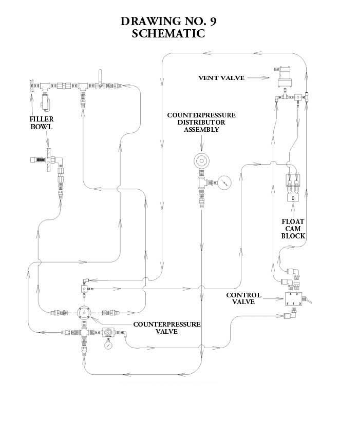
- The Uni-Level-Trol® system basically controls the pressure balance of the filler bowl in relation to the carbo-cooler (see bottom drawing).
- A single float ball is linked to a two-lobe cam which will activate two air switches which in turn will open or close one or the other of two valves.
- The vent valve will open or close upon demand of the float and cam assembly. When the level of liquid is lower than a pre-determined level, the valve will be opened by an air signal and allow the air in the filler bowl head space to be reduced. This causes a pressure unbalance (lower) and the liquid from the carbo-cooler will flow into the filler bowl.
- When the bowl liquid level is at the correct pre-determined level, the valve closes and the flow stops because of the pressure balance.
- This action continues repeatedly as the level decreases during the filling operation, thus replenishing the liquid in the bowl.
- If, for any reason, the liquid level in the bowl becomes too high the other lobe of the cam contacts the other air switch and will open the counter pressure valve (B). This valve is connected to the high pressure CO2 or air line through the rotary gland (I) of the filler and when opened will allow higher pressure air or CO2 (about 15 PSI above bowl pressure), to enter the filler bowl, thus pushing the liquid in the bowl back to the carbo-cooler. When the level is back to normal range the valve closes and the normal operation continues as before.
- The control pressure for the air valves is 35 PSI, this is set by air regulator.
- The operator can easily set the desired liquid level by rotating the cam assembly. Generally, the small bottles fill better with a low bowl level and larger bottles fill faster at the higher level.
- The relationship of the normal operating level and the counter pressure level is fixed by the cam lobes. Thus at any pre-determined level, the vent and counter pressure operation is fixed in relation to each other.
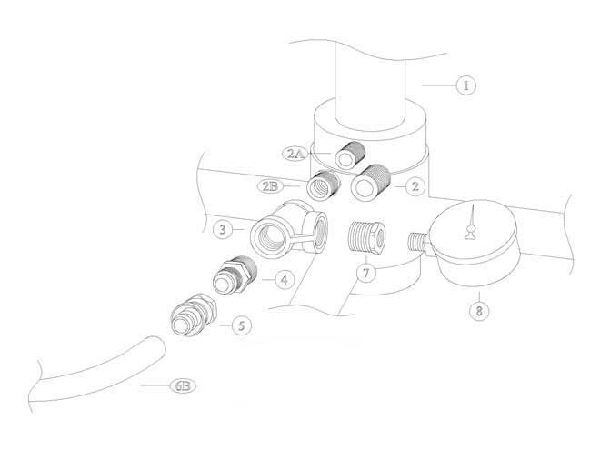
| PARTS LIST | ||
|---|---|---|
| REF # | PART # | DESCRIPTION |
| 1 | ———- | Existing Counter-pressure Distributor Assembly |
| 2 | ULT-50 | 1/2″ x Close S/S Nipple |
| 2A * | ULT-68-S | 3/8″ x 2″ S/S Nipple |
| 2B * | ULT-69 | 1/2″ x 3/8″ Reducing Bushing |
| 3 | ULT-62 | 1/2″ x 1/2″ x 1/2″ S/S Tee |
| 4 | ULT-30 | 1/2″ x 1/2″ Hose Connector |
| 5 | ULT-31 | 1/2″ Swivel Hose Connector |
| 6 | ULT-32 | 1/2″ I. D. Hose |
| 7 | ULT-52 | 1/2″ x 1/4″ S/S Reducing Bushing |
| 8 | ULT-61 | Pressure Gauge 0-160# S/S |
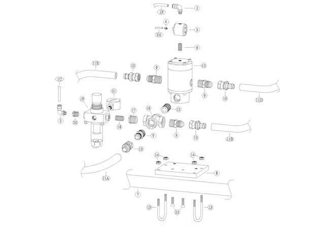
| PARTS LIST | ||
|---|---|---|
| REF # | PART # | DESCRIPTION |
| 1 | ULT-29 | 1/4″ O.D. Tubing |
| 2 | ULT-40-N | 90 Degree Tubing Connector (2 pcs. req.) |
| 3 | ULT-42-S | Valve Actuator |
| 4 | ULT-28-N | 1/16″ Barb Fitting |
| 5 | ULT-55-BK | 1/16″ I.D. Black Tubing-Connect to 6-H |
| 6 | ULT-43-S | 1/8″ x Close S/S Nipple |
| 7 | ———- | Existing Product Line/Tank Support Bar |
| 8 | ULT-37-A | Counterpressure Valve Mounting Bracket |
| 9 | ULT-30 | 1/2″ Hose Connector (4 pcs. req.) |
| 10 | ULT-31 | 1/2″ Swivel Hose Connector (4 pcs. req.) |
| 11 | ULT-32 | 1/2″ I.D. Hose |
| 12 | ULT-36-S | Counterpressure Valve (REPAIR KIT AVAILABLE) |
| 13 | ULT-37-B | 1/4″ – 20 S/S U-Bolt (2 pcs. req.) |
| 14 | ULT-02 | 1/4″ – 20 S/S Nut (4 pcs. req.) |
| 15 | ULT-50 | 1/2″ x Close S/S Nipple |
| 16 | ULT-49 | 1/2″ S/S Cross |
| 17 | ULT-52 | 1/2″ x 1/4″ S/S Reducing Bushing |
| 18 | ULT-53 | 1/4″ x Close S/S Nipple |
| 19 | ULT-39 | 1/4″ Pressure Regulator/Filter – 5 micron |
| 20 | ULT-44-S | 1/4″ x 1/8″ S/S Reducing Bushing |
| 21 | ULT-38-S | Pressure Gauge 0-60# S/S |
| 22 | ULT-57-B | 1/4″-20 x 1″ S/S Flat Head Screw (2 pcs. req.) |

| PARTS LIST | ||
|---|---|---|
| REF # | PART # | DESCRIPTION |
| 1 | ULT-48 | CO2 Counterpressure Inlet Adapter |
| 2 | ULT-07 | “O”-Ring |
| 3 | ULT-16-A | 7/8″ – 14 S/S Nut |
| 4 | ULT-47 | 1/2″ S/S Street Elbow |
| 5 | ULT-46 | 1/2″ S/S Check Valve (REPAIR KIT AVAILABLE) |
| 6 | ULT-30 | 1/2″ Hose Connector |
| 7 | ULT-31 | 1/2″ Swivel Hose Connector |
| 8 | ULT-32 | 1/2″ I. D. Hose (SEE SCHEMATIC) |
| 9 | ———- | Inside Wall of Filler Tank |

| PARTS LIST | ||
|---|---|---|
| REF # | PART # | DESCRIPTION |
| 1 | ———- | Existing 1/2″ Ball Valve |
| 2 | ULT-47 | 1/2″ S/S Street Elbow (2 pcs. req.) |
| 3 | ———- | Existing 1/2″ x Close Nipple |
| 4 | ———- | Existing 1/2″ Cross or ULT-49 1/2″ S/S Cross |
| 5 | ULT-50 | 1/2″ x Close S/S Nipple |
| 6 | ULT-51-A | 1/2″ S/S Ball Valve w/gauge |
| 7 | ULT-52 | 1/2″ x 1/4″ S/S Reducing Bushing |
| 8 | ULT-53 | 1/4″ x Close S/S Nipple |
| 9 | ULT-54-C | 1/4″ S/S Vent Valve (REPAIR KIT AVAILABLE) |
| 10 | ULT-43-S | 1/8″ x Close S/S Nipple (2 pcs. req.) |
| 11 | ULT-73 | 1/8″ Shuttle Valve |
| 12 | ULT-42-S | Valve Actuator (REPAIR KIT AVAILABLE) |
| 13 | ULT-29 | 1/4″ O.D. Tubing (SEE SCHEMATIC) |
| 14 | ULT-41-N | Tee Tubing Connector |
| 15 | ULT-28-N | 1/16″ Barb Fitting |
| 16 | ULT-55-WH | 1/16″ I.D. White Tubing-Connect to 4-G Drawing #7) (SEE SCHEMATIC) |
| 17 | ULT-40-N | 90 Degree Tubing Connector |
| 18 | ULT-72 | 1/4″ S/S Street EL |
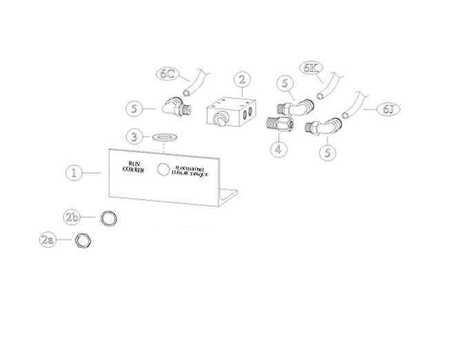
| PARTS LIST | ||
|---|---|---|
| REF # | PART # | DESCRIPTION |
| 1 | ULT-74 | Control Mounting Bracket |
| 2 | ULT-75 | Control Valve |
| 2A | SUPPLIED WITH ULT-75 | 15/32″ Nut |
| 2B | SUPPLIED WITH ULT-75 | 15/32″ Internal Tooth Lock Washer |
| 3 | ULT-77 | 1/2″ S/S Flat Washer |
| 4 | ULT-76 | 1/8″ x 1/8″ Extender |
| 5 | ULT-40-N | 90 Degree Tubing Connector (3 pcs. req.) |
| 6 | ULT-29 | 1/4″ O.D. Tubing (SEE SCHEMATIC) |
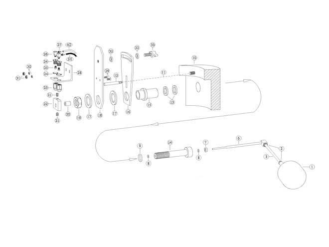
| PARTS LIST | ||
|---|---|---|
| REF # | PART # | DESCRIPTION |
| 1 | ULT-01 | Float Ball |
| 2 | ULT-02 | 1/4″ – 20 S/S Jam Nut (2 pcs. req.) |
| 3 | ULT-03 | Float Stem |
| 4 | ULT-55-WH | 1/16″ I.D. White Tubing-Connect to 16-G (Drawing #5) (SEE SCHEMATIC) |
| 5 | ULT-55-BK | 1/16″ I.D. Black Tubing-Connect to 5-H (Drawing #3) (SEE SCHEMATIC) |
| 6 | ULT-04 | Float Arm & Shaft Assembly |
| 7 | ULT-05 | Spacer |
| 8 | ULT-05-A | Teflon Coated “O”-Ring (2 pcs. req.) |
| 9 | ULT-07 | “O”-Ring |
| 10 | ———- | Inside Wall of Filler Tank |
| 11 | ———- | 1/4″ x .400 Deep Drilled Hole |
| 12 | ULT-10 | Bracket Pin |
| 13 | ULT-08 | Spacer (2 pcs. supplied) |
| 14 | ULT-06-1 | Float Shaft Hub |
| 15 | ULT-09 | Support Bushing |
| 16 | ULT-13 | Stationary Adjusting Plate |
| 17 | ULT-14 | Lower Spacer (2 pcs. req.) |
| 18 | ULT-15 | Movable Adjusting Plate |
| 19 | ULT-16 | 7/8″ – 14 S/S Nut |
| 20 | ULT-18-A | Cam Spacer .625 Long |
| 21 | ULT-19 | 1/4″ – 20 x 3/8″ S/S Set Screw (2 pcs. req.) |
| 22 | ULT-20 | Cam Block |
| 23 | ULT-21-N | Actuator/Ball & Housing (2 pcs. req.) |
| 24 | ULT-27-N | Housing with Star Washer (2 pcs. req.) |
| 25 | ULT-26 | Actuator Seal (2 pcs. req.) |
| 26 | ULT-28-AN | #10-32 Elbow (2 pcs. req.) |
| 27 | ULT-28-N | 1/16″ Barb Fitting (2 pcs. req.) |
| 28 | ULT-22 | Actuator/Mounting Bracket |
| 29 | ULT-25 | #10-24 x 1/2″ S/S Flat Head Screw (2 pcs. req.) |
| 30 | ULT-24 | #10 S/S Lock Washer (2 pcs. req.) |
| 31 | ULT-23 | #10-24 S/S Nut (2 pcs. req.) |
| 32 | ULT-12 | Upper Spacer (2 pcs. req.) |
| 33 | ULT-11 | 3/8″ – 24 x 3/4″ Thumb Screw |

| PARTS LIST | ||
|---|---|---|
| REF # | PART # | DESCRIPTION |
| 1 | ———- | Existing 1/2″ x Close Nipple |
| 2 | ———- | Existing 1/2″ x 1/2″ x 1/2″ Tee |
| 3 | ULT-50 | 1/2″ x Close S/S Nipple (3 pcs. req.) |
| 4 | ULT-46 | 1/2″ S/S Check Valve (REPAIR KIT AVAILABLE) |
| 5 | ULT-62 | 1/2″ x 1/2″ x 1/2″ S/S Tee |
| 6 | ULT-51 | 1/2″ S/S Ball Valve |
| 7 | ———- | Existing Relief Valve |
| 8 | ULT-30 | 1/2″ x 1/2″ Hose Connector (2 pcs. req.) |
| 9 | ULT-31 | 1/2″ Swivel Hose Connector (2 pcs. req.) |
| 10 | ULT-32 | 1/2″ I.D. Hose (SEE SCHEMATIC) |
| 11 | ———- | Inside Wall of Filler Tank |

