
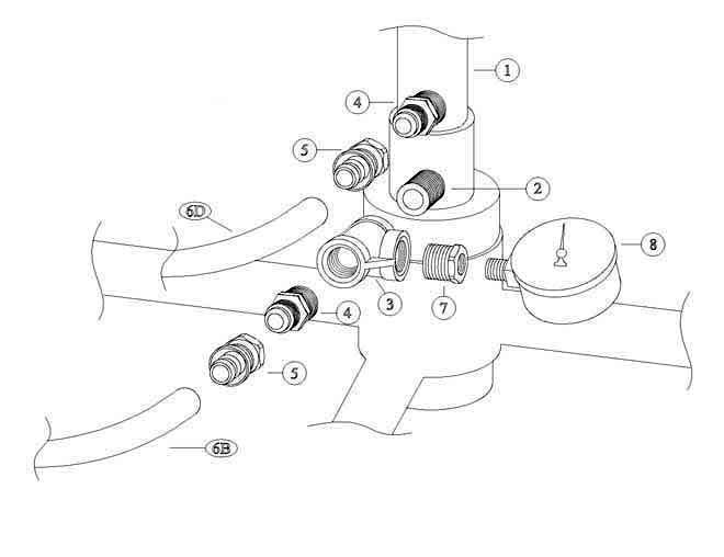
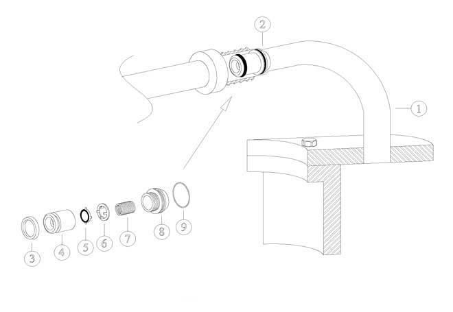
| PARTS LIST | ||
|---|---|---|
| REF # | PART # | DESCRIPTION |
| 1 | ———- | Existing Counterpressure Distributor Assembly |
| 2 | ULT-50 | 1/2″ x Close S/S Nipple |
| 3 | ULT-62 | 1/2″ x 1/2″ x 1/2″ S/S Tee |
| 4 | ULT-30 | 1/2″ x 1/2″ Hose Connector (2 pcs. req.) |
| 5 | ULT-31 | 1/2″ Swivel Hose Connector (2 pcs. req.) |
| 6 | ULT-32 | 1/2″ I. D. Hose (SEE SCHEMATIC) |
| 7 | ULT-52 | 1/2″ x 1/4″ S/S Reducing Bushing |
| 8 | ULT-61 | Pressure Gauge 0-160# S/S |
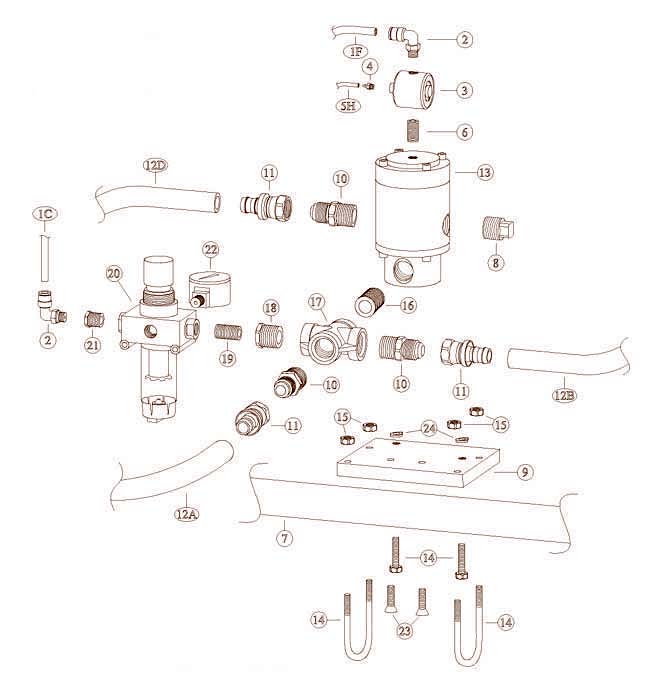
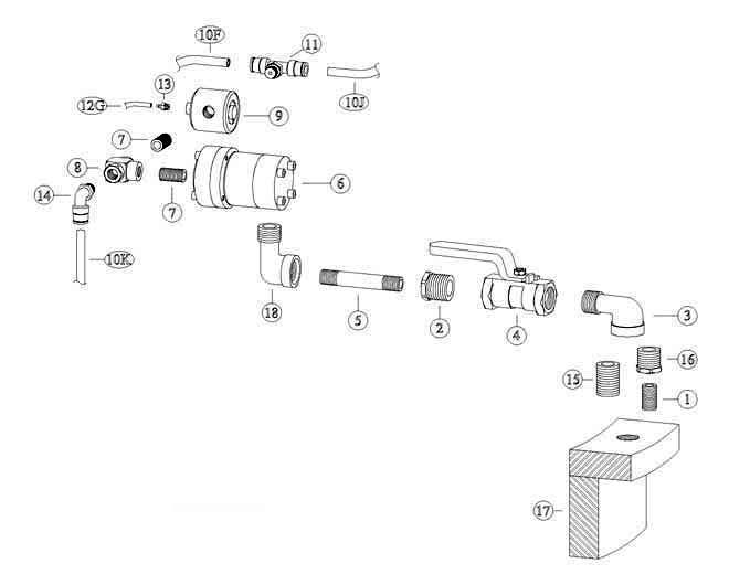
| PARTS LIST | ||
|---|---|---|
| REF # | PART # | DESCRIPTION |
| 1 | ULT-29 | 1/4″ O.D. Tubing (SEE SCHEMATIC) |
| 2 | ULT-40-N | 90 Degree Tubing Connector (2 pcs. req.) |
| 3 | ULT-42-S | Valve Actuator (REPAIR KIT AVAILABLE) |
| 4 | ULT-28-N | 1/16″ Barb Fitting |
| 5 | ULT-55-BK | 1/16″ I.D. Black Tubing (connect to 5-H, drawing #4) (SEE SCHEMATIC) |
| 6 | ULT-43-S | 1/8″ x Close S/S Nipple |
| 7 | ———- | Existing Bowl Support Bar or (*Product Line) |
| 8 | ULT-50-A | 1/2″ S/S Plug |
| 9 | ULT-37-A | C/P Valve Mounting Bracket |
| 10 | ULT-30 | 1/2″ x 1/2″ Hose Connector (3 pcs. req.) |
| 11 | ULT-31 | 1/2″ Swivel Hose Connector (3 pcs. req.) |
| 12 | ULT-32 | 1/2″ I.D. Hose (SEE SCHEMATIC) |
| 13 | ULT-36-S | Counterpressure Valve (REPAIR KIT AVAILABLE) |
| 14 | ULS-38-N | 1/4″-20 x 1 �” S/S Bolt (2 pcs. req.) |
| 14 | ULT-37-B | (*)1/4″ – 20 S/S U-Bolt (2 pcs. req.) |
| 15 | ULT-02 | 1/4″-20 S/S Nut (2 pcs. req.) |
| 16 | ULT-50 | 1/2″ x Close S/S Nipple |
| 17 | ULT-49 | 1/2″ S/S Cross |
| 18 | ULT-52 | 1/2″ x 1/4″ S/S Reducing Bushing |
| 19 | ULT-53 | 1/4″ x Close S/S Nipple |
| 20 | ULT-39 | 1/4″ Pressure Regulator/Filter – 5 Micron |
| 21 | ULT-44-S | 1/4″ x 1/8″ S/S Reducing Bushing |
| 22 | ULT-38-S | �Pressure Gauge 0-60# |
| 23 | ULT-57-B | 1/4″-20 x 1″ S/S Flat Head Screw (2 pcs. req.) |
| 24 | MCD-09 | 1/4″ S/S Lock Washer (2 pcs. Req.) |
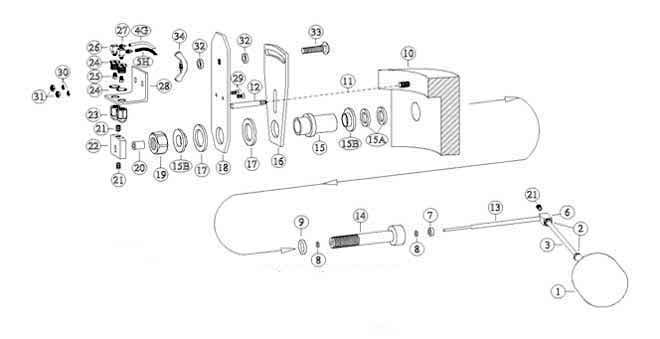
| PARTS LIST | ||
|---|---|---|
| REF # | PART # | DESCRIPTION |
| 1 | ULT-01 | Float Ball |
| 2 | ULT-02 | 1/4″-20 S/S Jam Nut (2 pcs. req.) |
| 3 | ULT-03 | Float Stem |
| 4 | ULT-55-WH | 1/16″ I.D. White Tubing (connect to 12G, drawing #6) (SEE SCHEMATIC) |
| 5 | ULT-55-BK | 1/16″ I.D. Black Tubing (connect to 5H, drawing #3) (SEE SCHEMATIC) |
| 6 | ULT-04-A | Float Arm Hub |
| 7 | ULT-05 | Spacer |
| 8 | ULT-05-A | Teflon Coated “O”-Ring (2 pcs. req.) |
| 9 | ULT-07-A | “O”-Ring |
| 10 | ———- | Inside Wall of Filler Bowl |
| 11 | ———- | 1/4″ x .400 Deep Drilled Hole |
| 12 | ULT-10 | Bracket Pin |
| 13 | ULT-04-B | Float Arm Shaft |
| 14 | ULT-06-1-C | Float Shaft Hub |
| 15 | ULT-09 | Support Bushing |
| 15A | ULT-08-A | Spacer (2 pcs. supplied) |
| 15B | ULT-09-A | S/S Support Bushing Adapter (2 pcs. req.) |
| 16 | ULT-13 | Stationary Plate |
| 17 | ULT-14 | Lower Spacer (2 pcs. req.) |
| 18 | ULT-15-A | Movable Adjusting Plate |
| 19 | ULT-16-B | 3/4″-16 S/S Jam Nut |
| 20 | ULT-18-A | Cam Block Spacer |
| 21 | ULT-19 | 1/4″-20 x 3/8″ S/S Set Screw (3 pcs. req.) |
| 22 | ULT-20 | Cam Block |
| 23 | ULT-21-N | Actuator/Ball & Housing (2 pcs. req.) |
| 24 | ULT-27-N | Housing with Star Washer (2 pcs. req.) |
| 25 | ULT-26 | Actuator Seal (2 pcs. req.) |
| 26 | ULT-28-AN | #10-32 Elbow (2 pcs. req.) |
| 27 | ULT-28-N | 1/16″ Barb Fitting (2 pcs. req.) |
| 28 | ULT-22 | Actuator/Mounting Bracket |
| 29 | ULT-25 | #10-24 x 1/2″ S/S Flat Head Screw (2 pcs. req.) |
| 30 | ULT-24 | #10 S/S Lock Washer (2 pcs. req.) |
| 31 | ULT-23 | #10-24 S/S Nut (2 pcs. req.) |
| 32 | ULT-12 | Upper Spacer (2 pcs. req.) |
| 33 | ULT-11-A | 3/8″-16 x 1″ S/S Carriage Bolt |
| 34 | ULT-11-B | 3/8″-16 S/S Wing Nut |
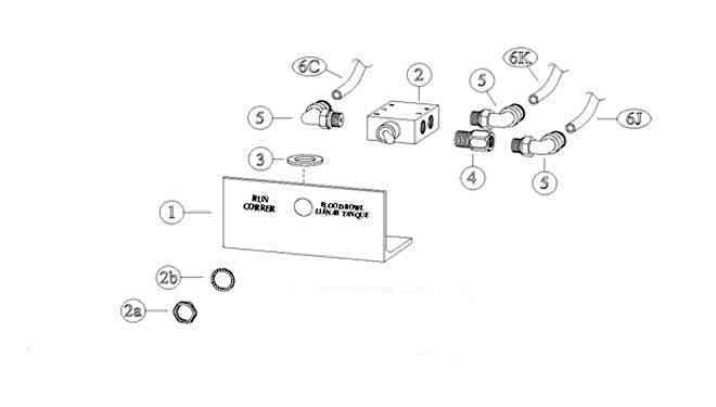
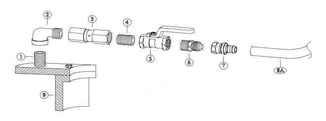
| PARTS LIST | ||
|---|---|---|
| REF # | PART # | DESCRIPTION |
| 1 | ULT-74 | Control Mounting Bracket |
| 2 | ULT-75 | Control Valve |
| 2A | * | 15/32″ Nut |
| 2B | * | 15/32″ Internal Tooth Lock Washer |
| 3 | ULT-77 | 1/2″ S/S Flat Washer |
| 4 | ULT-76 | 1/8″ x 1/8″ Extender |
| 5 | ULT-40-N | 90 Degree Tubing Connector (3 pcs. req.) |
| 6 | ULT-29 | 1/4″ O.D. Tubing (SEE SCHEMATIC) |
| PARTS LIST | ||
|---|---|---|
| REF # | PART # | DESCRIPTION |
| 1 | ULT-78 | 3/8″ x Close S/S Nipple |
| 2 | ULT-52 | 1/2″ x 1/4″ S/S Reducing Bushing |
| 3 | ULT-47 | 1/2″ S/S Street Elbow |
| 4 | ULT-51-A | 1/2″ S/S Ball Valve w/gauge |
| 5 | ULT-70 | 1/4″ x 3″ S/S Nipple |
| 6 | ULT-54-C | 1/4″ S/S Vent Valve (REPAIR KIT AVAILABLE) |
| 7 | ULT-43-S | 1/8″ x Close S/S Nipple (2 pcs. req.) |
| 8 | ULT-73 | 1/8″ Shuttle Valve |
| 9 | ULT-42-S | Valve Actuator (REPAIR KIT AVAILABLE) |
| 10 | ULT-29 | 1/4″ O.D. Tubing (SEE SCHEMATIC) |
| 11 | ULT-41-N | Tee Tubing Connector |
| 12 | ULT-55-WH | 1/16″ I.D. White Tubing (connect to 4-G, drawing #4) (SEE SCHEMATIC) |
| 13 | ULT-28-N | 1/16″ Barb Fitting |
| 14 | ULT-40-N | 90 Degree Tubing Connector |
| 15 | ULT-50 | 1/2″ x Close S/S Nipple |
| 16 | ULT-65 | 1/2″ x 3/8″ S/S Reducing Bushing |
| 17 | ———- | Existing Filler Bowl Inner Wall |
| 18 | ULT-72 | 1/4″ S/S Street EL |
| PARTS LIST | ||
|---|---|---|
| REF # | PART # | DESCRIPTION |
| 1 | ———- | Existing Counterpressure Lines (1″) |
| 2 | ULT-46-A | UNI-Check Valve Assembly (2 or 3 pcs. req.) (REPAIR KIT AVAILABLE) |
| 3 | ULT-46-A4 | Cone “U”-Cup |
| 4 | ULT-46-A2 | Threaded Cone |
| 5 | ULT-46-A7 | Poppet Seat |
| 6 | ULT-46-A6 | Poppet Spacer |
| 7 | ULT-46-A5 | Spring |
| 8 | ULT-46-A1 | Threaded Disc |
| 9 | ULT-46-A3 | Disc “O”-Ring |
| PARTS LIST | ||
|---|---|---|
| REF # | PART # | DESCRIPTION |
| 1 | ———- | Existing Adapter Or ULT-50 |
| 2 | ULT-47 | 1/2″ S/S Street Elbow |
| 3 | ULT-46 | 1/2″ S/S Check Valve (REPAIR KIT AVAILABLE) |
| 4 | ULT-50 | 1/2″ x Close S/S Nipple |
| 5 | ULT-51 | 1/2″ S/S Ball Valve |
| 6 | ULT-30 | 1/2″ x 1/2″ Hose Connector |
| 7 | ULT-31 | 1/2″ Swivel Hose Connector |
| 8 | ULT-32 | 1/2″ I.D. Hose (SEE SCHEMATIC) |
| 9 | ———- | Inside Wall of Filler Bowl |
